AMT SyncSys Ethernet Motion
& I/O Control
Hardware

Two controllers, one footprint

The controllers do the time-critical work in hardware and firmware: step pulses up to 500,000 steps per second, ramps, limits, homing and E-Stop. Both controllers share the same footprint and connections: 8.0 × 5.2 in (203 × 132 mm), Ethernet interface and opto-isolated I/O.

AMT SyncSys Ax

Ethernet motion and I/O controller
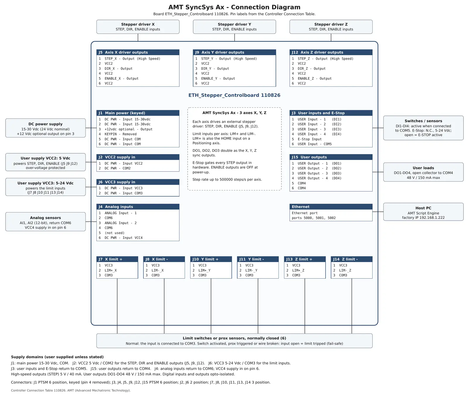
  • 3 axes — STEP, DIR and ENABLE to external stepper or servo drives
  • Coordinated motion — not CNC interpolated motion
  • 16 to 500,000 steps/s per axis, trapezoidal ramps
  • Three modes per axis: Positioning, Feeder-Index, Spindle
  • LIM+ and LIM− per axis; LIM+ also serves as HOME
  • 4 digital inputs, 4 digital outputs, 2 analog inputs
  • Position-synchronized outputs: DO1, DO2, DO3 for X, Y, Z
  • E-Stop gates every step output in hardware

AMT SyncSys IO

The same controller for I/O only — no motion
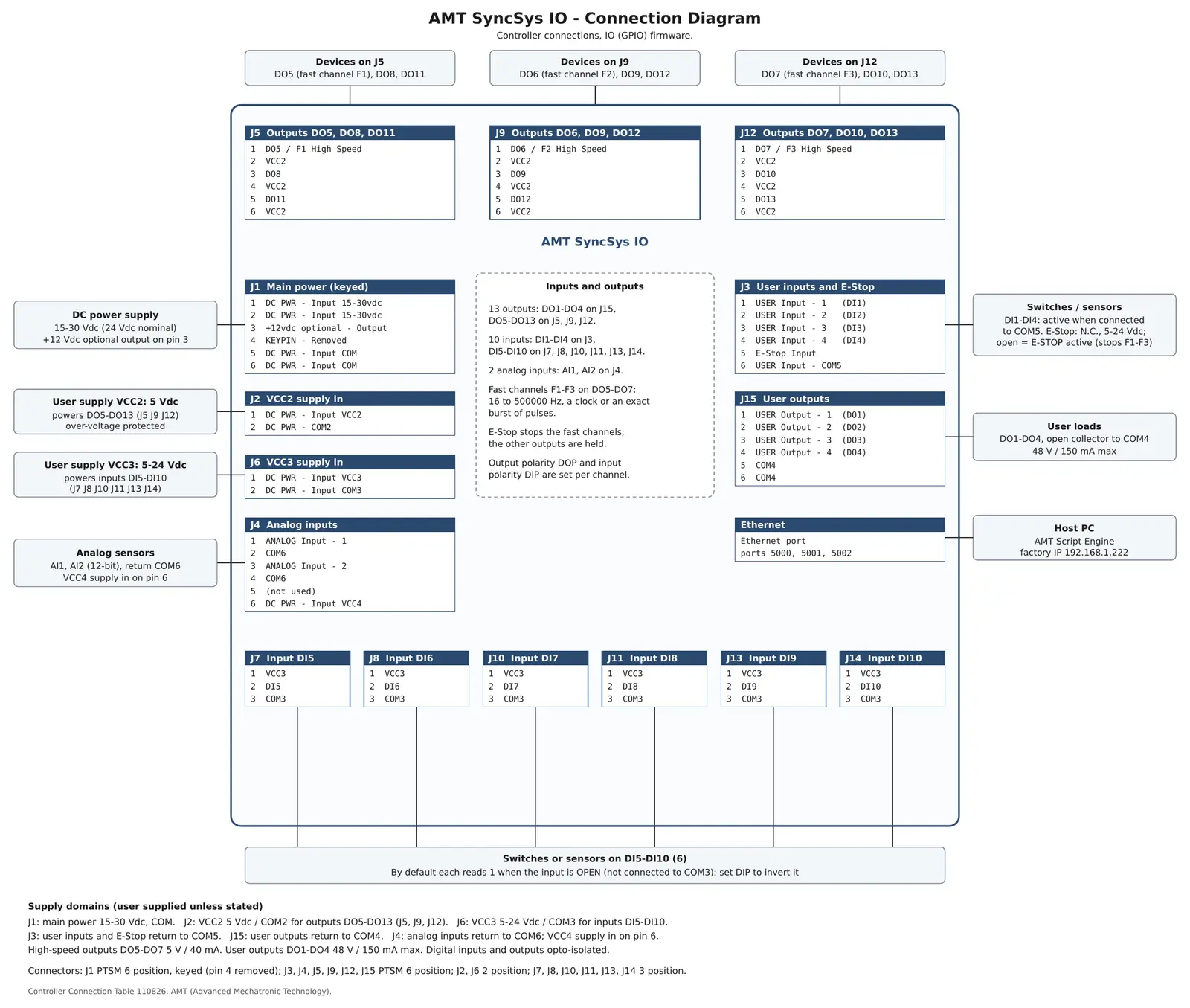
  • 13 digital outputs
  • 10 digital inputs
  • 2 analog inputs
  • 3 fast pulse channels, 16 Hz to 500 kHz — a steady clock or an exact burst of pulses*
  • E-Stop stops the fast channels and holds the other outputs
  • Input and output polarity set per channel

* Fast pulse channels are provided in a coming firmware release.

15–30 VdcSupply, 24 Vdc nominal; reverse-polarity protected
Opto-isolatedDigital inputs and outputs
48 V / 150 mAUser outputs, open collector
8.0 × 5.2 × 1.5 in203 × 132 × 38 mm, without mating plugs
Drawings
Board layout and connections

Pluggable PTSM terminal connectors throughout; the main power connector is keyed. Click a drawing to open the full PDF.
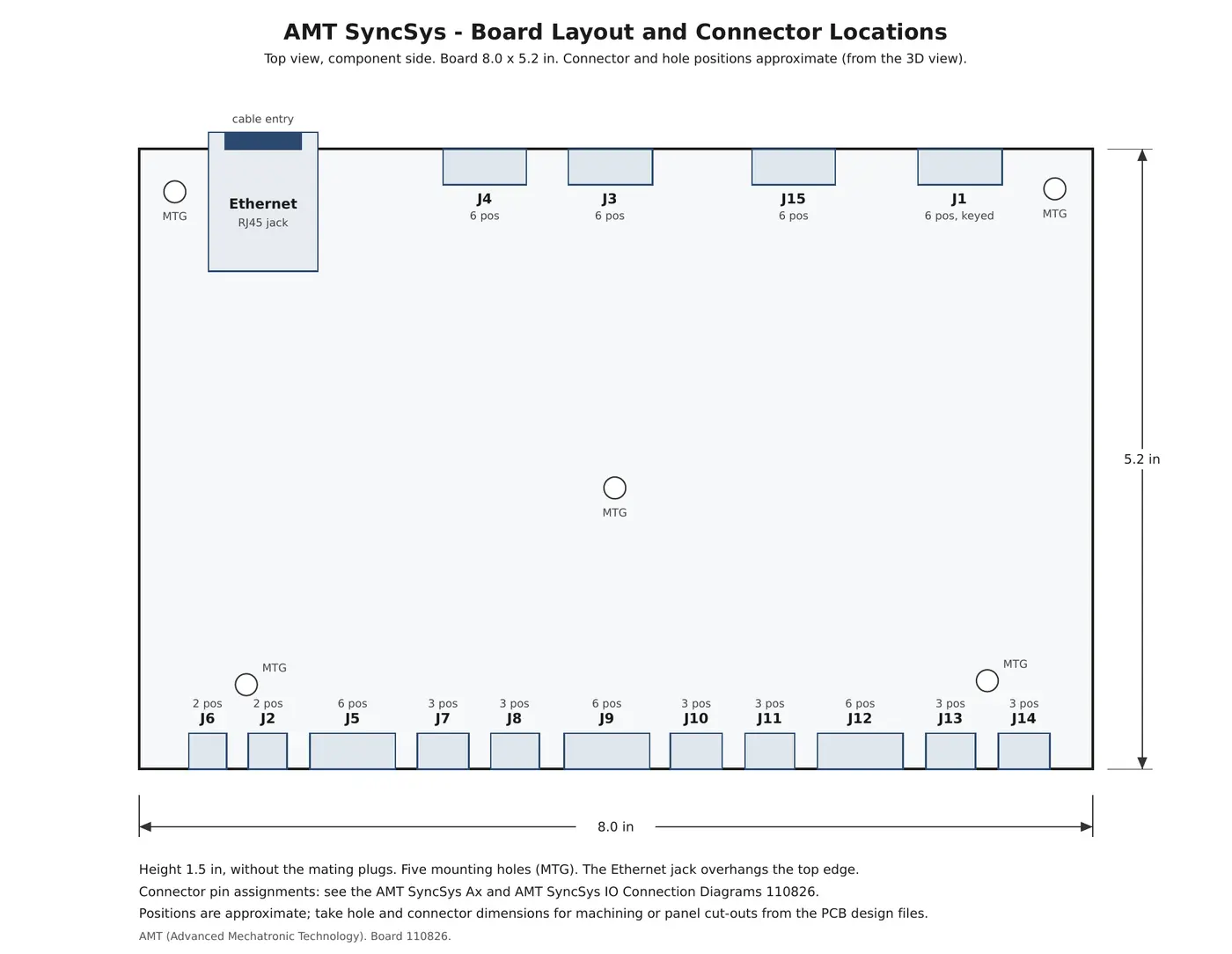
AMT SyncSys board layout and connector locations
Board Layout and Connector Locations Open PDF →
Growing the System
Several controllers, one script

The same AMT Script Engine that runs one controller also runs several — no separate edition is needed. One machine can use up to 2 SyncSys Ax and 4 SyncSys IO controllers on the same network.

  • Up to 6 axes: X Y Z on the first motion controller, U V W on the second
  • Up to 48 inputs, 60 outputs, 12 analog inputs and 12 fast pulse channels, numbered on from one controller to the next — a script simply says OUTPUT,17,ON
  • Only what is installed is accepted: the editor and the script check refuse an axis, input or output the machine does not have
  • Every controller is checked at connect; E-Stop and every stop act on all controllers
  • Moves, synchronized outputs and pulses are timed within each controller — put axes and outputs that must be timed together on the same controller
Safety
Fail-safe by design
  • E-Stop: a normally-closed loop; an open loop (pressed, or a broken wire) stops the machine. On SyncSys Ax it gates every step output in hardware.
  • Limit inputs: normally closed; a broken wire reads as tripped.
  • Watchdog: with the communications watchdog set, a controller stops on its own if the PC or the network stops talking to it.
  • Low-voltage detection: the controller makes itself safe and records how it last shut down.
  • Start-up: driver ENABLE outputs are off at power-up.
Safety note: the E-Stop input is a control function. A machine's safety circuit must still remove power through its own safety-rated hardware.
Ordering
Order items
AMT SyncSys Ax3-axis motion and I/O controller
AMT SyncSys IOI/O controller, no motion
AMT Script EngineOperator and runtime software, for one controller or up to 6 (2 SyncSys Ax and 4 SyncSys IO)
AccessoriesMating plug connectors

1- and 2-axis versions are available as OEM specials. Full specifications →

Discuss your machine.

Describe the sequence, the axes and the I/O. We'll confirm the configuration and provide a quotation.

Request a Quote →